Getting Root on an Ambarella A5s Camera
Intro
I'm a software engineer by trade, but lately I've been interested in embedded systems. Specifically, gaining root access and running custom code or firmware on consumer IoT devices. I have very little experience with embedded systems, but I decided to try and get into an old security camera I had lying around.
Meet my test subject: an all-in-one security camera and security system released in 2015. With features like video streaming, motion notifications, auto-arming, and a siren alarm, it was a good solution for me to secure my apartment back then.
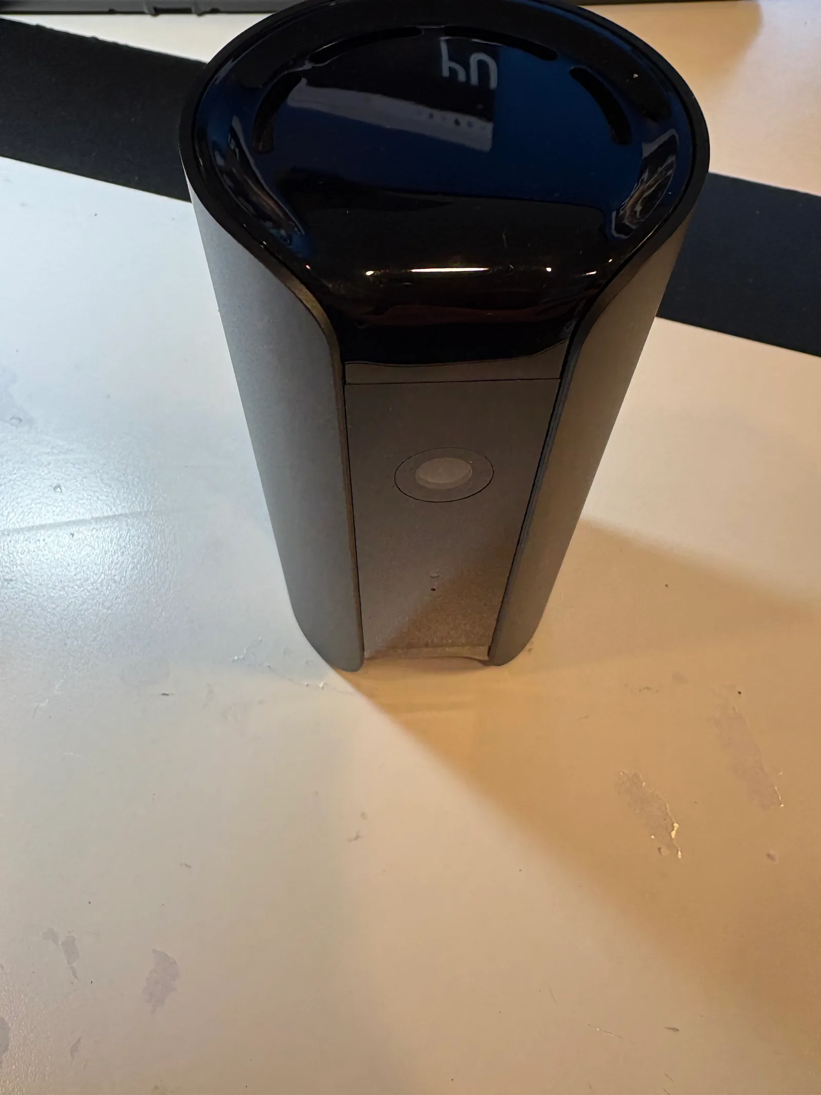
Unfortunately for me, its manufacturer took securing the device very seriously. None of the typical methods for getting access to IoT devices worked on it. But the challenge just made it more interesting for me, and despite my lack of experience I eventually managed to get in. Here is a video showing custom code running on two of these cameras with control over the speaker, LED, IR shutter, and siren.
Claude Code was instrumental during this project. I used it for all aspects of the project including brainstorming, analysis, and of course writing code. It was also a huge learning aid for me since I could ask questions directly about what we were doing and test my understanding of each step. I used the latest model available, Opus 4.6, and later switched to Opus 4.7 when it was released.
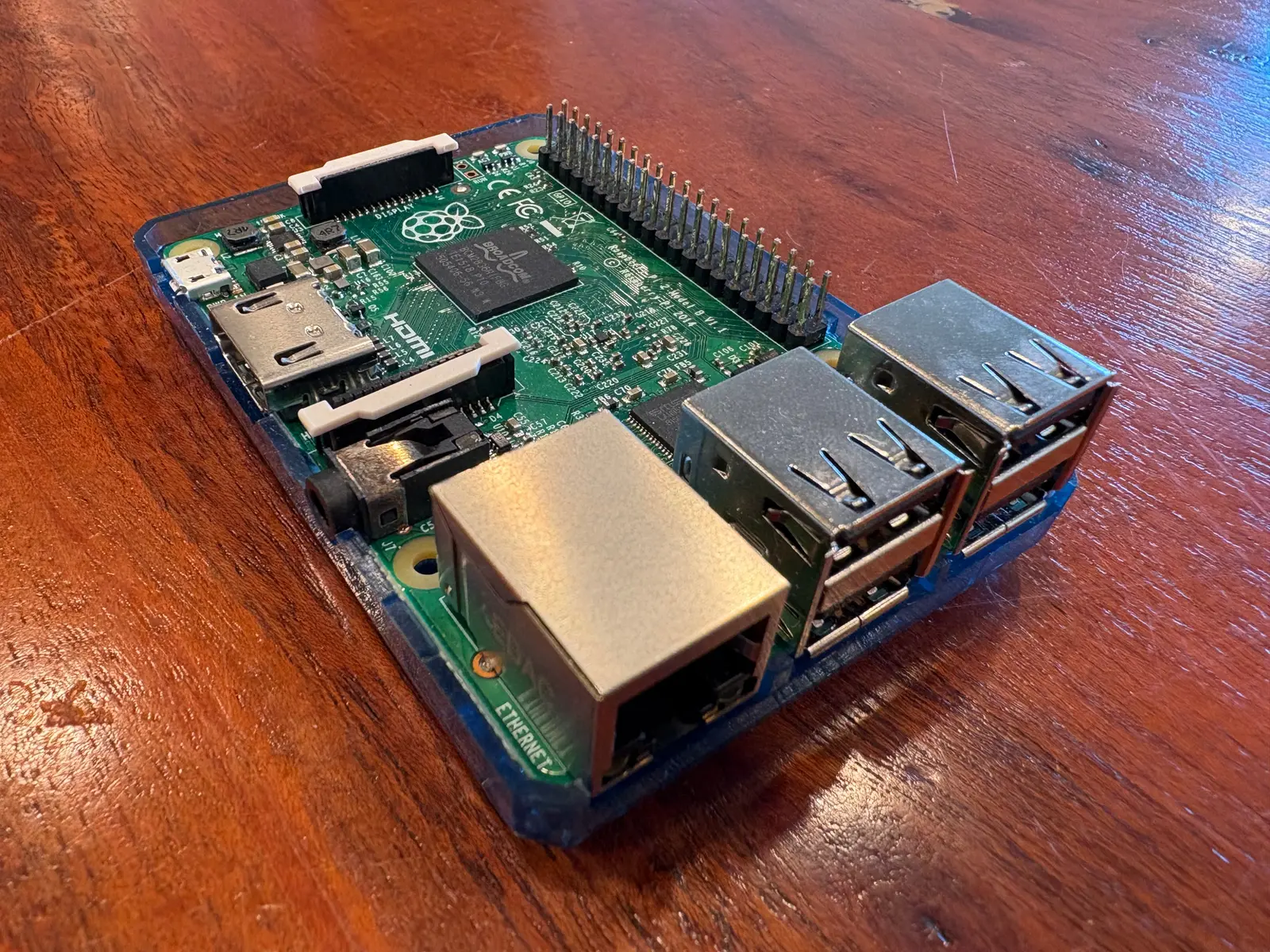
Additionally, the Raspberry Pi was extremely useful for interfacing with the camera. It is easily programmable and has a lot of tools for dealing with embedded systems. I used a Raspberry Pi 2 Model B.
One of the first things I learned was that a device like this camera is a full-blown Linux system. It has a full ARM processor, RAM, storage, Wi-Fi, and Ethernet. Several components are packaged together into one Ambarella SoC (system on chip). Special hardware like buttons, sensors, and LEDs are controlled via GPIO (general purpose IO) pins on the SoC. The SoC also has dedicated hardware for dealing with video processing and encoding. The embedded world has its own set of system buses for connections between the SoC and peripheral chips, and these are different from what I am familiar with in the PC world. Additionally, Ambarella only makes device information available to manufacturers. Drivers and manuals are generally not available to end users.
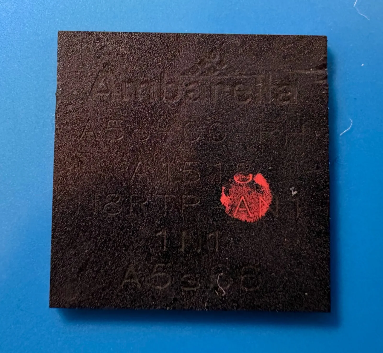
Specs of the unit I have:
| Spec | Detail |
|---|---|
| SoC | Ambarella A5s (ARM1136J-S, ARM11-based) |
| RAM | SK hynix H5TQ2G63GFR — DDR3, 256 MB |
| NAND flash | SK hynix H27U2G8F2C — 256 MB parallel (ONFI) NAND, main firmware storage |
| EEPROM | Atmel AT24C256C (U29) — I²C, 256 Kbit / 32 KB; device identity/config |
| Camera | 1080p Full HD, M12 lens, 147° wide-angle, flat glass front |
| Night vision | IR LEDs + mechanical switchable IR-cut filter (day/night) |
| Sensors | PIR motion, temperature, humidity, air quality (VOC) |
| Audio codec | TI TLV320AIC3101 (I²C-0 @ 0x18) |
| Speaker amp | SG Micro SGM4890 (3 W mono Class-D) |
| Siren | 90+ dB piezo buzzer |
| Wireless | 802.11 b/g/n 2.4 GHz only + Bluetooth 4.0 LE (CSR1010), on a separate round PCB |
| Ethernet | 10/100 Mbps RJ45 |
| Ports | Micro-USB (5 V/2 A power), Ethernet, 3.5 mm TRRS audio (setup) |
| OS | Custom embedded Linux on the Ambarella platform |
Network
The easiest way in is through an open door. A telnet or SSH service with a blank or easy-to-guess password would give us shell access. A local HTTP app or API might expose admin controls. If any exposed service is using a server with an old version, we could check for known vulnerabilities.
Unfortunately, the camera doesn't expose any network services. All ports on both Wi-Fi and Ethernet are closed.
The camera does make outgoing network connections to the vendor's cloud to stream video, send events, and receive configuration and firmware updates. It turns out that the firmware updates are fully automatic and only happen via this channel. There is no manufacturer supported way to download or update the firmware manually. However, if we put the camera on a network isolated from the internet, we could fake the responses from the vendor's cloud, which would allow us to do anything to the device that the real cloud could do.
The camera prevents this by securing all cloud connections with mTLS. This means that all data is encrypted, and both sides of the connection cryptographically authenticate the other. We cannot pass this authentication check without modifying the trusted certificates on the device, which itself requires root access.
UART
UART is a very simple scheme for data transmission and virtually all embedded chips support it. By default, it is exposed to Linux as a serial console, and Linux will use it for logs and as a login console. If we can find the physical UART interface and login as root, we'd have full access.
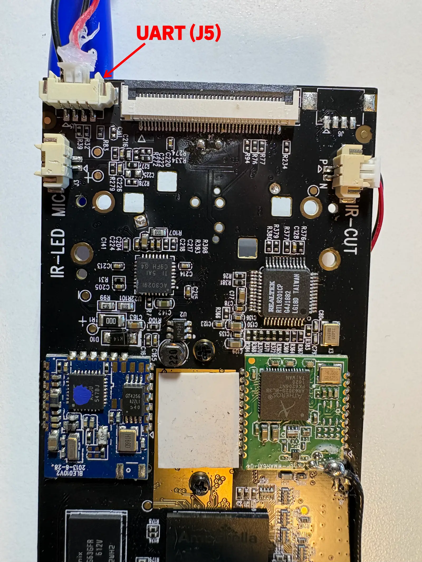
On the camera, UART is routed to a 4-pin connector on the bottom edge of the main board. The pins are ground, receive, transmit, and VCC (not used). The Raspberry Pi supports UART via its GPIO pins, and it happens to run at the same 3.3 V as the camera. After connecting the two devices with some jumper cables... the camera would no longer boot.
The issue was that the RX line was being held high by the Pi while the camera was off. This partially powered the SoC, causing some corrupt state and preventing the SoC from booting correctly. By forcing the Pi to hold that pin low during boot, the camera starts up normally. After finding the correct baud rate, we were able to get full UART access. Here is what the camera sends on boot:
Boot from secondary partition
loading sec to 0xc0208000
���������C100G1611991}���F��
����	����
����	��
And that's it. No kernel logs, no login prompt. Just two messages from the boot loader and then some kind of binary data.
UART bootloader interrupt
It appears that Linux serial access is disabled on the camera, so we can't get in that way. But there is another option. The messages that we do see come from the bootloader. If we can access the bootloader shell, we could modify the Linux kernel cmdline. Using that, we could skip the normal initialization and even skip login, dropping directly into a root shell. Skipping initialization breaks a lot of stuff in the system, but we would at least be able to read and write the root filesystem.
Typically you just hold some key (by sending it over UART) during the early boot to enter the bootloader shell. We tried the common keys (enter, newline, escape), all with no effect. We later found out that the camera uses a custom-built bootloader that completely skips this key check and always boots immediately with hard-coded options.
USB / DFU recovery mode
The camera has a USB port, and the SoC supports several different boot options, including booting over USB. If we could boot over USB into our own kernel, we might be able to get enough working to at least read and write to the flash.
We connected the camera's USB port to another Linux host and rebooted the camera. The USB connection on the host fails right away:
usb 1-1.2: new full-speed USB device number 67 using dwc_otg
usb 1-1.2: device descriptor read/64, error -32
usb 1-1.2: device descriptor read/64, error -32
The host is requesting a descriptor from our camera and it's just not getting any response. The camera is ignoring all traffic on the USB data lines. It's possible they aren't even connected to the SoC; USB can easily be used for power only.
JTAG
JTAG is a low-level debug protocol for chips. If we can get JTAG access to the CPU embedded in the SoC, we'd have direct access to registers and processor state. We could run any instructions we want at the Linux kernel level. Gaining shell access would be tedious but doable.
There are many test points on the board. Through some trial and error, we were able to identify which test points made up the JTAG interface. I soldered some leads to candidate points and connected them to the Pi. Claude wrote code for the Pi to scan through the possible options and identify the correct JTAG pins.
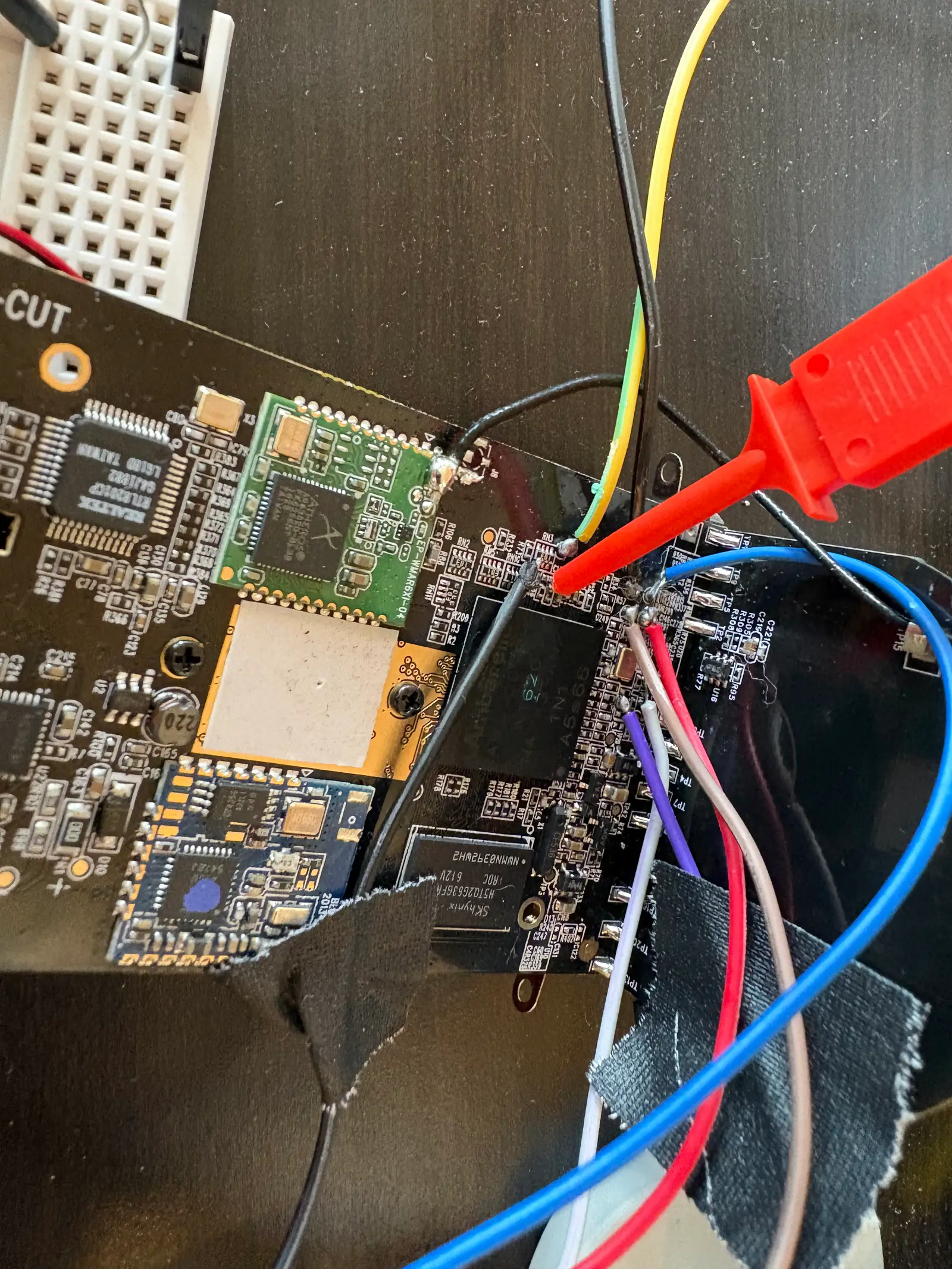
After identifying the pins, it worked. The chip responded correctly to JTAG commands. We were able to communicate with the debug TAP on the processor, but we were not able to do anything useful. Attempts to halt or access normal registers were ignored. JTAG on this chip was locked down to prevent exactly what we were trying to do. It's possible the manufacturer's engineers used unlocked dev chips or had some other secret way to unlock, but we weren't getting in this way.
EEPROM Read
Examining the camera's main board, we found a small chip used for non-volatile memory. Based on the datasheet, it was a 32 KB I²C EEPROM in an 8-lead TSSOP package. I²C is a bus commonly supported by embedded SoCs, like our Ambarella. To read it, I got some absolutely tiny probes and carefully attached them to the four pins needed for reading. These probes were so fragile that strain relief was essential, which I made from some bits of cardboard and tape.
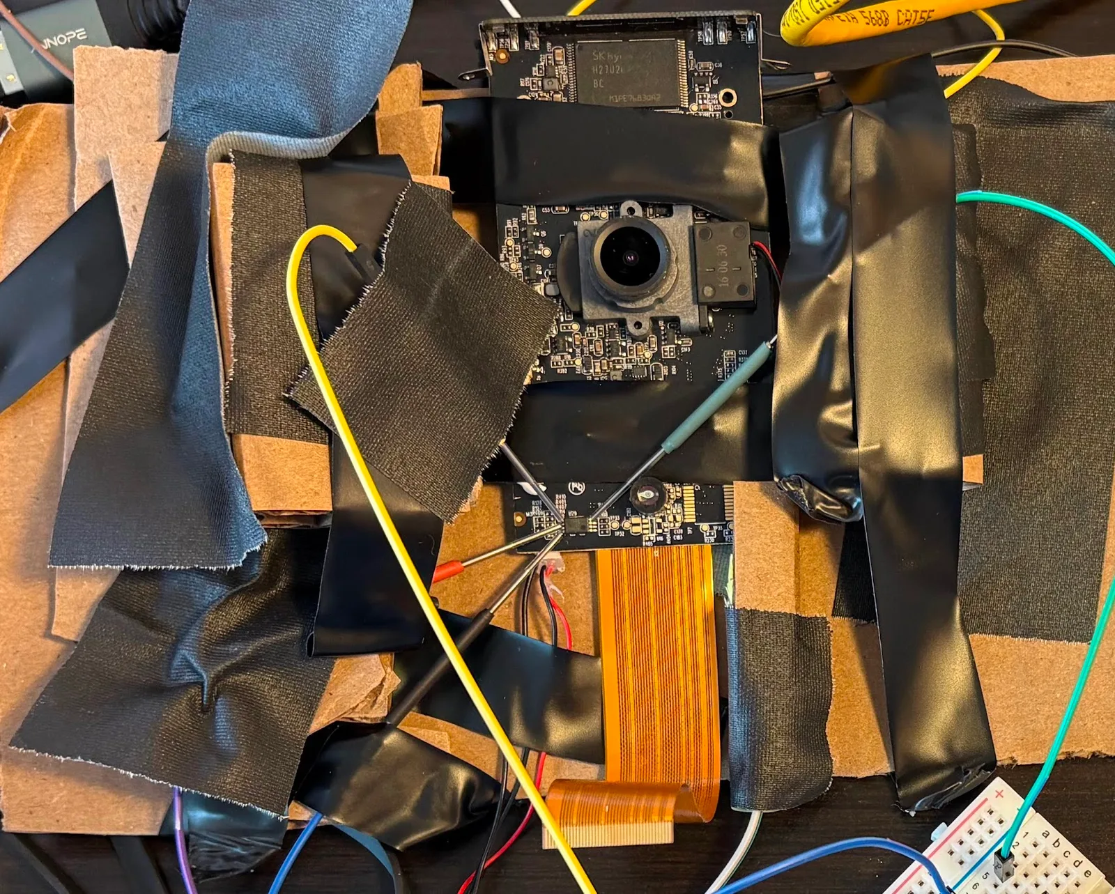
We might get lucky and find some config data that we could overwrite to enable UART, network, or boot access. The Pi supports I²C over the GPIO pins, so we used it to read the chip. Here are the full contents stored on the chip:
00000000  aa aa aa aa aa aa aa aa  aa aa aa aa aa aa aa aa  |................|
*
00000100  10 00 43 4e 2d 53 4e 2d  30 30 30 30 31 37 35 31  |..CN-SN-00001751|
00000110  38 37 00 00 00 00 00 00  00 00 00 00 00 00 00 00  |87..............|
00000120  00 00 00 00 00 00 00 00  00 00 00 00 00 00 00 00  |................|
00000130  00 00 00 00 00 00 00 00  00 00 00 00 00 00 00 89  |................|
00000140  0c 00 43 31 30 30 47 31  36 31 31 39 39 31 00 00  |..C100G1611991..|
00000150  00 00 00 00 00 00 00 00  00 00 00 00 00 00 00 00  |................|
00000160  00 00 00 00 00 00 00 00  00 00 00 00 00 00 00 00  |................|
00000170  00 00 00 00 00 00 00 00  00 00 00 00 00 00 00 87  |................|
00000180  ff ff ff ff ff ff ff ff  ff ff ff ff ff ff ff ff  |................|
*
00008000
32 KB just to store two serial numbers. Nothing useful here.
NAND Desolder
If we could read the firmware, we could analyze it to look for a way in. Maybe there is a secret backdoor or some old software included that has a known vulnerability. Many vendors publish firmware online so that users can upgrade manually. But this manufacturer doesn't -- all updates are done automatically and over mTLS.
We can't download the firmware, but we do have a copy -- on the NAND chip that is soldered to the camera's board. We could read the data off the chip directly, bypassing the SoC and getting the raw data. But this chip has a lot of pins, and they are tiny. The smallest probes I could find were still way too big to attach to individual pins on this chip.
The solution was to desolder the NAND chip and use a breakout board for this particular package. The breakout board clamps down on all the pins at once and routes them all to much larger pins that we can easily connect to the Pi. My soldering skills are rudimentary and there is no way I'd be able to resolder this chip once it was removed. So I got a second camera to serve as a donor. With some difficulty, I was able to desolder the chip without destroying it.
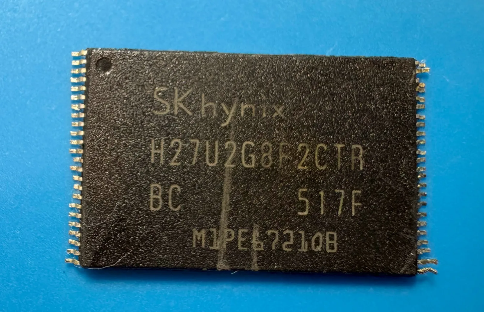
I found the datasheet for the NAND chip, which gave us the pinout as well as a few capacitors and resistors to add. After connecting it to the Pi, I had Claude read the datasheet and write code to communicate with the chip. It worked! The chip responded to read commands and sent data back. After a few optimizations, we read the full 264 MiB from the chip in about 2 minutes.
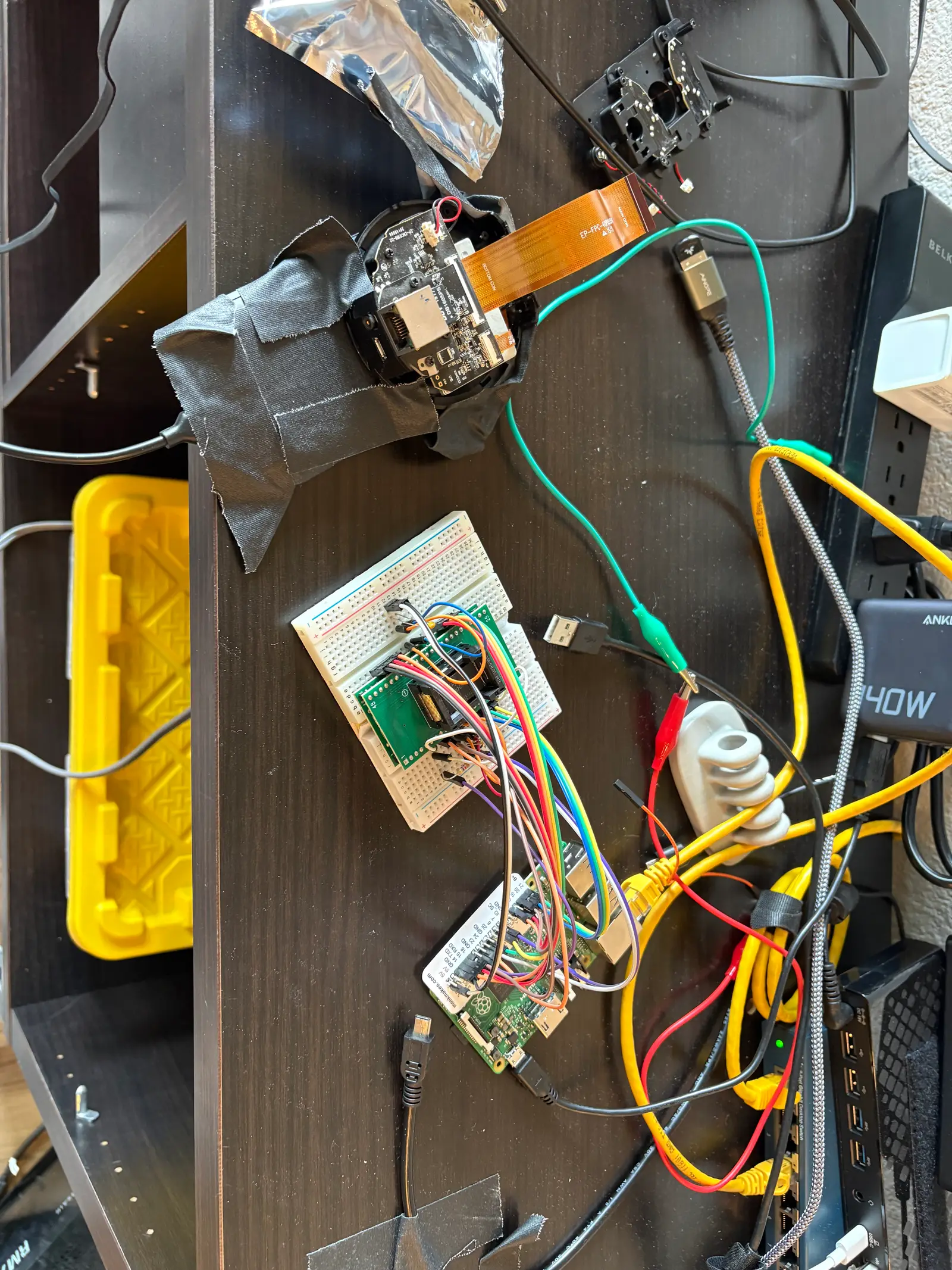
Dumping gave us the raw data: 131,072 pages, each with 2048 data bytes and 64 out-of-band bytes. The out-of-band bytes contain error correction data. Normally the SoC handles this, but since we bypassed it for our read, we needed to deal with it. Claude was able to correctly guess the error-correction scheme (the same as used in Linux), but there was a concerning number of uncorrectable errors -- over 43%!
Unused blocks were largely corruption-free. Most of the corruption was concentrated in files in the rootfs. Files for initialization and running services were corrupt, making analysis difficult.
Boot ROM
Due to the corruption in the earlier NAND dump, it wasn't very useful. After diligently searching online, I was able to find a somewhat thorough datasheet for the SoC. It had two pieces of information of particular relevance to us: the full chip pinout, and the fact that setting a single pin would put the chip into USB boot mode. Our earlier USB tests failed, but maybe if we set this pin we would be able to use the camera's USB port to boot in USB mode.
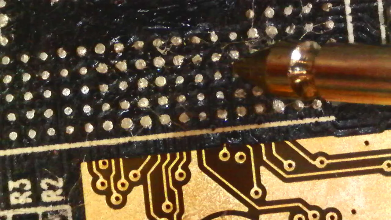
The SoC is a BGA package, meaning that all the pins are underneath the chip. I carefully desoldered the SoC on the donor board so that I could access the traces for those pins. Using a multimeter and a microscope, I traced a few interesting pins including that USB boot mode pin. I traced that pin to a test point on the other side of the board. I soldered a lead to the same point on the other camera and hooked it up to the Pi.
usb 1-1.2: new full-speed USB device number 69 using dwc_otg
usb 1-1.2: device descriptor read/64, error -32
usb 1-1.2: new high-speed USB device number 70 using dwc_otg
usb 1-1.2: language id specifier not provided by device, defaulting to English
usb 1-1.2: New USB device found, idVendor=4255, idProduct=0001, bcdDevice= 0.00
usb 1-1.2: New USB device strings: Mfr=1, Product=2, SerialNumber=3
It worked! Holding the USB boot pin low on boot puts the chip into USB boot mode. The chip runs some code from its own ROM that enables USB and waits for commands over USB, though we didn't yet know what commands it accepts.
The boot dance
I was able to find a USB boot utility program for this chip online. Watching USB traffic, we determined that the boot rom only accepts three simple commands: read word, write word, and exec address.
To actually run anything useful, the DRAM needs to be initialized early during boot. Normally, this is done by a tiny bootstrapper program loaded from NAND, but here we do it using read and write commands over USB.
We ran a test to make sure things work. Once it sent *** PAYLOAD HELLO 0xCAFE1337 *** over UART, we knew it worked. We had successfully run our own code on the camera.
Sending data using the write command is quite slow. To speed things up, we send a minimal bootloader program that supports bulk USB transfer. We jump to that, and then use this faster mode in the next stage.
Then we dump the contents of the NAND over UART. This reads page by page, and NAND error correction is handled automatically by the SoC -- none of the noise that had wrecked our off-chip read. To make this fast, we run a sweep over UART baud rates to find the fastest stable one. We also add some basic framing with CRC and retries. Now we finally have a backup of the NAND!
Next, we want to unlock the real bootloader. This will let us get the actual NAND partition data as well as read and write the kernel cmdline. The bootloader is at a known position on the NAND, so we extract and disassemble it. We patched a branch instruction to always jump to the amboot shell instead of autobooting the device. When this is run over USB, we get a boot shell on the real bootloader!
At one point Claude was having some difficulty identifying the location in the binary where it decides whether to boot or show the shell. I don't do much reverse-engineering, but my programmer's intuition was good enough that I was able to point Claude to the right code block. I felt quite satisfied that I was able to find it faster than Claude -- being faster than Claude at something coding related is getting very rare!
Linux shell
We now have the ability to read the NAND. We can also write to it using a similar method. We can also run arbitrary code at boot or set the kernel cmdline and boot to Linux. From here there are several ways to get a root shell.
We did it by updating the NAND data so that the Linux init scripts start an SSH server. First, we split the NAND dump into partitions using the partition debug information from the boot shell. Then, we extract the filesystem for the partition holding the rootfs. We build a dropbear SSH server for this system and add an init script to start it at boot. Finally, we rebuild the rootfs filesystem image and boot the camera into a custom program that writes just that partition to the NAND. Once that is configured, we don't need to worry about the boot process anymore -- we can just get a root shell anytime by logging in via SSH over the network.
Working features
Using the existing drivers already in the firmware, all basic Linux functionality works fine, including serial, filesystems, and networking. GPIO control also works: we can control the status LED, IR shutter, and siren, and we can read the button state.
After some finagling, Claude was able to get the speaker to work with standard Linux tools. The hardware seems to ignore certain sampling frequencies, but we can just resample audio files before playing them. The speaker is tiny, so the quality is not very good, but chiptune-style music (like in the demo video) sounds decent.
We were able to get the camera to work in a very low-res, low-fps mode. But the camera in this device isn't just a camera. There is a whole video pipeline with hardware-offloading for things like encoding, exposure, and signal processing. Normally, there is a user-level application that runs to configure the drivers and enable a full-resolution video stream. But we don't want to run that, because it waits for instruction from the cloud to start video and it also does other things like check for updates and configure Wi-Fi. The drivers, application, and hardware are all proprietary and closed, so it would take a bunch more reverse-engineering to figure out the proper configuration.
It would be interesting to replace the firmware with an open source one like OpenIPC. They don't have support for Ambarella chips yet, and it would take significant work to deal with the closed drivers, especially those for the video pipeline.
Appendix
Mystery UART binary data
We analyzed the binary data sent over UART and it appears to be a simple custom binary protocol with message types, sequence number, and CRC. The messages sent over UART appear to be an initial ACK, the device's serial number, and then regular heartbeats. We did try to generate and send messages using the same framing back over UART, but we never observed any change in behavior.
NAND corruption solution
I didn't know it at the time, but the NAND chip is fast and sensitive enough that electrical reflection within the wires themselves was enough to derail the read. I don't have an electrical engineering background, and my earlier successes with the Pi encouraged me to try and read the NAND this way. Interestingly, Opus 4.6 was also confused by the results -- it was convinced that there was a defect within the NAND chip itself. Later, when Opus 4.7 became available, I let it analyze the results and it immediately identified the problem. It even came up with a solution -- lower the voltage on the Pi GPIO pins. With that change, we were able to get a good read with only 0.09% uncorrectable errors (likely genuinely bad cells on the flash). By this point, though, we had long since pulled a clean dump straight through the SoC, so the fixed off-chip read was never actually needed -- just a loose end finally tied off.
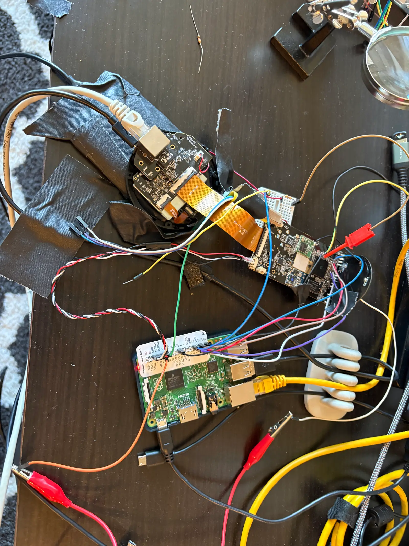
Agent friendly bench setup
AI Agents perform best when they have a good loop with proper feedback where the agent can judge the results of its actions. This requires a bit of extra setup when working with a physical device like this camera.
The camera has a status LED which shows different colors and modes depending on the device status. It cycles through a few different states during boot, so it is a good indicator for debugging. I pointed an old Android phone directly at the LED and had Claude set up a basic HTTP camera server on the phone. When combined with a detection script, this provided Claude with live status of that LED.
We rebooted the camera many, many times during this project by power cycling it. In order to let Claude control the power to the device, I plugged it into a Wi-Fi smart plug that had an open-source CLI tool. Later in the project, we needed to use the single USB port on the camera for both power and data. For that, I plugged the camera into a dedicated USB port on the Pi which could be power-cycled in software.
The agent itself ran on a dedicated VM with root access granted to the agent. This allows the agent to install tools and configure attached hardware. A Pi could be used instead, but mine is a bit old and the specs are too low for this.
For Wi-Fi and Ethernet testing, I used USB adapters and mapped them to the agent VM for the agent to configure as needed.
Any leads attached to the camera board were connected to Pi GPIO pins. The agent could access the Pi over SSH.
To keep everything straight for the agent, I maintained a single markdown file that described the state of everything on the bench, including all connections.
Disclosures
All research was done on devices that I own.
Kudos to the manufacturer -- I didn't find any vulnerabilities that would put its users at risk. However, I don't claim that no vulnerabilities exist. My goal was to repurpose my own device, not to break into others' devices.
Unique device identifiers have been replaced with representative values.
I did this work independently. The manufacturer and its partners own the original firmware, design, and trademarks.